| Home |
| Specifications |
| History of Hull #42 |
| Equipment & Systems |
|
Manuals & Data Sheets |
| Projects |
| Photo Gallery |
| Stories |
| Links |
| About Us |
| Blog |
Completed Projects
It is my intention to photo-document these here as I complete them, but I'm way behind on web updates.
- Add a Galvanic Isolator - January, 2010
- New A/C shore power panel - March, 2010
- Remove and rebed opening port in head - April, 2010
- Genoa Car Repair - June, 2010
- Engine Replacement - Oct, 2010 - Mar, 2011
- Rebuild Exhaust - March, 2011
- Convert to Fresh Water Cooling< - April, 2011
- Upgrade to Self-Tailing Winches - October, 2011
- Rebuild Deck Hatches - Dec, 2011 - Apr, 2012
- Add Battery Monitor - March, 2012
Future Projects
These are in no particular order or priority.
- Remove and rebed stanchions
- Rebed chainplates
- Add lazy jacks
- Redesign topping lift
- Add boom vang
- Add masthead fly
- Add charge combiner
- Add a Dodger
- Add blocks and halyard winch for spinnaker
- Add anchor washdown pump
- Modify traveler for 3:1 purchase
- Replace cabin sole
Galvanic Isolator
This was a pretty easy project. Total time was about 2 hrs, and part of that was spent hunting for the crimp connectors. But first some background.
Soner or later, every boat owner gets introduced to the galvanic corrosion that happens when you put two dissimiliar metals that are electrically connected into saltwater. You quickly learn to install and maintain an appropriate number of zincs to protect your valuable underwater hardware, such as through-hulls and prop shafts.
What some don't know, however, is that it's possible to do everything right and still have galvanic corrosion! The problem happens when you're connected to shore power. Even if all your A/C devices, like your battery charger, are transformer isolated, there's still the safety ground. This is connected directly to your boat's system ground, to which all your underwater hardware is bonded. As a result your boat's ground, through the marina's wiring, is now connected to every other boats grounds and hardware! And if any of them aren't properly protected, they'll cause a galvanic current that'll start eating your zincs! This uses them up too quickly, and then least noble of your hardware starts going.
The obvious solution is to disconnect the safety ground. But this is a serious safety hazard unless you are absolutly sure that everything is transformer isolated, and remains that way. So, what we really want, is something in series with the safety ground that doesn't conduct most of the time, but will conduct the full service current in case of a short.
It turns out that there is such a device. It depends on the fact that virtually all galvanic circuits are driven by only a few tenths of a volt. A silicon diode drops about 0.6 volt. Below this, it doesnt conduct at all. Above this, it conducts heavily. Since 0.6 volt isn't really enough, we put two in series for 1.2 volt. And since diodes only conduct in one direction, we put another pair in parallel in the opposite direction.
This is basis of a galvanic isolator. Real-world devices are more complicated, including things like fail-safe, A/C leakage bypass, and monitoring. But at their heart, there are four diodes.
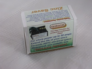
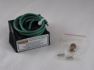
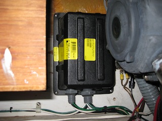
So, now on to the actual project! After some research, I chose the Yandina GI-50N. This is a no-frills, 50-Amp unit from Yandina Ltd.
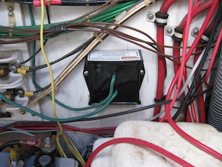
The first thing was to disconnect the shore power and size up the A/C wiring to locate
the ground wire and find a place to mount the isolator.
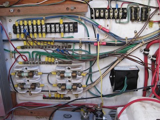
As you can see, Dolce Vita still has the original minimal A/C wiring from Pearson,
with 33 years and 8 owners worth of additions!
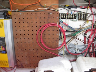
A little cable rearranging opens up space for the isolator, which mounts with two wood screws.
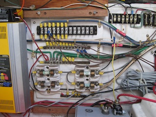
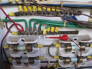
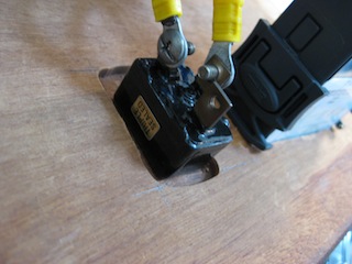
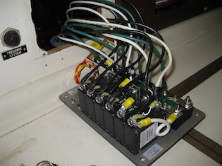
Next, I had to find and disconnect the ground wire from the shore power connector.
Note the copper buss bar with all the green wires. This is the central grounding point
for all the boat. The ground connection from the shore power inlet connector terminates here.
Since it's difficult to trace it through the bundle of identicallly colored wires, it was
necessary to use an ohmmeter to trace the correct wire. One by one, I disconnected the
wires and checked for continunity between the disconnected end and the ground pin on
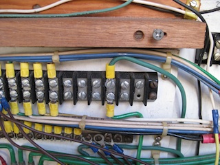
the shore power connector. Once found, I moved it to an unused position on a terminal strip.
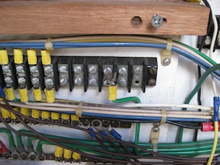
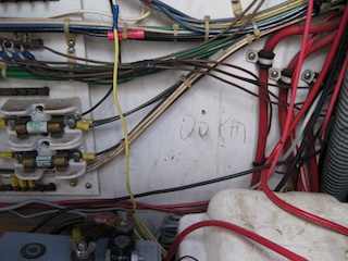
Lastly, I crimped two lugs onto the two wires from the isolator. One of these went to the
new terminal position, and the other went to the original position of the ground wire.
New A/C Shore Power Panel
Although this was, in principle, a straightforward project, the implementation was somewhat time-consuming. I originally estimated 5 - 6 hours, but the reality came in closer to 20 hours! This was due, in part, to my tendency to obsess over details, but also due to the tedious task of tracing and removing the old AC wiring from the boat's tie-wrapped wireing harness without rewiring the whole boat! In addition, I was extremely cautious in the parts that involved cutting large holes in the interior cabin bulkheads, as I wanted a clean, professional-looking installation. And of course, no project like this is complete without a few surprises!
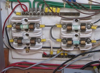
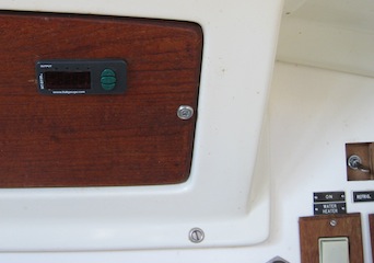
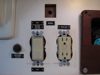
As previously mentioned, Dolce Vita came equipped with the original minimal AC wiring from Pearson. This consisted of 4 large cartridge fuses hidden behind a protector panel inside of the port cockpit locker. The shore hot and neutral leads were each protected by a 30 Amp fuse, and there were 2 branch circuits, each protected by their own fuse. Inside the cabin, there were no switches to control the branches or the main, only a pair of outlets (one in the galley and one in the head), and a switch for the hot water heater. This meant that everything (but the HW) was live whenever the shore power was plugged-in.
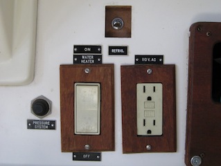
The switch that is visible in the square cutout is the DC power for the cold-plate referigeration system that was installed by a previous owner.
The first part of this project was coming up with a plan. I wanted to install a modern circuit-breaker-based panel with breakers for the main and at least four individual branch circuits. It looked like there would be room for this where the outlet, water-heater switch, and cold-plate switch were located. The outlet and cold-plate switch would have to be relocated, and the hot water switch could be eliminated as it's function would be taken over by one of the breakers.
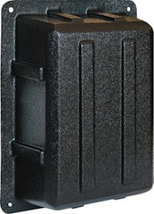
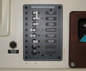
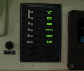
After looking at many panels, I selected the Blue Sea 8027 panel. This panel provides a dual-breaker 30 Amp main, three 15 Amp breakers, and provides space for 3 more. It also provides power-on indicators for the main and all breakers, a reverse-polarity indicator, label backlights, and a set of 30 labels. And it's dimensions were compatable whth the space I had available. I orderded it, along with an extra 15 Amp breaker, from Defender, as they had the best price by far. I also purchased the back panel cover to go with it.

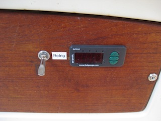
From here the job proceeded in three phases. First, I tackled moving the cold-plate switch. I wanted to move it next to the temperature controller and display, which is mounted on the teak panel directly beneath the companionway. I thought this would go quickly, as the wires were long enough, and all I should have to do was drill a hole and remount the switch. Silly me! When I got the teak panel off, I discovered that it was 1/2 inch thick, and the collar on the cold-plate switch would not reach all the way through it! This required removing the teak in order to route out the back by 1/4 inch, and this, in turn, required disconnecting all the other instrumentation mounted on that piece of teak! So, what should have taken a few minutes got spread out over two days. After reassembly, a label-maker completed the task.
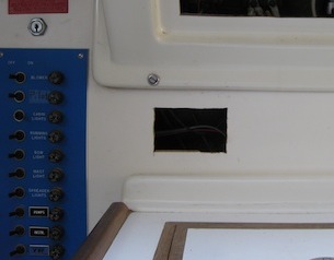
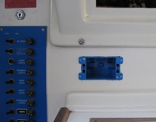
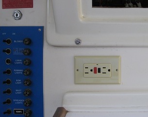
Next, I tackled relocating the outlet. After a lot of thought, discussion, and getting the blessing of the Admiral, I decided to move it to the starboard side of the bulkhead beneath the teak beneath the companionway. This would get it away from the sink area, and close to an out-of-the-way level place to park various chargers and power bricks. With the teak panel temporarily moved aside to provide easy access to the back of the bulkhead, I carefully marked out a rectangle that would accomodate a plastic "old work" outlet box. These install from the front, and lock in place with a pair of swingout "ears" attached to the mounting screws. Using an old magazine to protect the wiring behind the bulkhead, and with great trepidation, I carefully drilled 1/2 inch holes in the corners of the rectangle, and then used a saws-all to cut out the rectangle. By using a sharp, fine-toothed blade (actually meant for metal) I was able to cut a clean hole without splintering or chipping the edges. Rather that trying to reuse the existing GFI outlet, I simply purchased a new one.
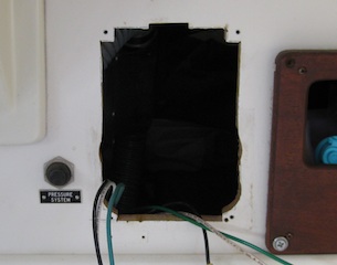
Now the stage was set for the main act: Cutting out the hole for the new panel and wiring it up. When I removed the warped teak trim plates from the outlet and switch I got my next surprise. There were no mounting boxes! The builder had simply used a hole saw to cut two large overlapping holes in the bulkhead, and screwed the outlet and the switch directly to the bulkhead! The connections were sealed with big blobs of silicone.
The next surprise came when I tried to position the panel cutout template. The outside edges of the round holes exceeded the width of the cutout. In addition, the square hole was taller than the top of the template! Fortunately, the panel has a generous shoulder past the cutout, and I was able to center the template so that the extra wide & extra tall parts wouldn't show past the edges of the panel. I traced the cutout template, held my breath, and started in with the saws-all. The results were not exactly pretty, but the panel would cover it. I positioned the panel carefully, and marked and drilled the corner mounting screwholes.

Now it was time to string all the wires. This was quite tedious, as it involved starting with the hot (black) wire for each device, determining the associated neutral (white) and safety-ground (green) wires for that circuit, unthreading them out of the wiring harness, and rerouting them to the new panel. This was made vastly more difficult by the fact that a previous owner had not paid attention to wire color, and many DC circuits were also wired with green and white wires! This whole process had to be repeated for every circuit, all while crouched within the confines of the port cockpit locker. In the case of the battery charger, the wires were all of the wrong color, too short, and connected with wirenuts (!!!), so I ripped them out and replaced them with proper wire.
At this point, I want to digress a little about wires.
Stranded primary wiring is a complex subject. Tinned vs untinned, number of strands, AWG vs SAE wire gauges, THHN insulation, oil & gas resistance, water resistance, and the list goes on. Generally what I've found is that marine grade wire is tinned, uses AWG wire gauges (SAE wire gauges are smaller for the same gauge!), and has more and finer strands than industrial and automotive wire, making it more resistant to vibration fatigue. It is gas & oil & water resistant, and has slightly thicker insulation than industrial grade THHN wire. It is also expensive.
Some people claim that, since marine wire terminals should be sealed with adhesive-lined shrink tubing, it is acceptable to use untinned industrial wire. While this may be true in theory, its always difficult to be sure the end is really sealed. And even if it is, one nick in the covering and salt water will get in and start eating the bare copper. It seems better to take a "belt and suspenders" approach and use tinned wire AND seal the ends.
Originally, since my boat already has almost all the wiring done with industrial-grade THHN, I was going to use the same thing, but carefully seal the ends. A knowledgable friend, whose opinion I respect, called this a "major mistake", pointing out all the above facts about marine grade wire, as well as one other. It turns out that, despite the thicker insulation, marine grade wire is much more flexible than THHN wire. This is due to both the finer strands and a softer insulation. THHN wire has a hard, nylon outer jacket. This is designed to make it slippery, so its easier to string through conduits. But it also makes it stiffer. This stiffness would become really important later when trying to bend and stuff fifteen wires on the fully-wired panel back into the restricted space inside the back cover. So, I bit the bullet and used expensive marine grade wire wherever I had to extend or replace.
Once this decision was made, I fitted the back cover with a couple of plastic feedthroughs, mounted it behind the bulkhead, and fed all the wires through. When crimping on the ring terminals and butt splices, I found that the uninsulated ones were easier to properly seal than the insulated ones. On the insulated ones, you had to use a larger diameter heat-shrink tubing to get over the insulator, and it doesn't always shrink down enough to seal the end.
Once all the connections were complete and tested, I carefully stuffed all the wires into the box and screwed the panel in place. I was quite pleased with the results.
At this point, there was still one more detail to attend to: the backlight system. This was another one of those "details" that I obsessed over, so I left it for last. The backlights consist of a set of green LEDs, fed from a single on-board regulator. This regulator needs 12 to 24 V DC. I measured the actual current draw, and its only about 50 milliamps (0.050 A).
My dilemma was, where to power this from? Since the whole point of the backlights is to be able to find the correct breakers in the dark, putting it on the cabin lights circuit didn't seem to make sense. A dedicated circuit seemed overkill, and I didn't have one available anyway. Like many boats, Dolce Vita's DC distribution panel is undersized. (a future upgrade project!). I considered putting it directly on the power bus ahead of any switch. It would be on whenever the battery selector switch was on. But I was unhappy with the idea that it would be drawing power even when we were off of shore power. Finally, it occured to me that the only time you need to see the labels is when you're on shore power, so why not run the backlights off of shore power? It'll be on when you need it, and won't drain battery power when you don't.
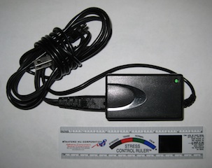
Initially, I was going to build my own 12 V supply from a small transformer, a diode and a capacitor. But I went thru my junk box and found an old 12 V power brick that was as small as anything I could bulid. And it wasn't a "wall wart" style. The two sets of wires would allow for an easy hookup. Since the power cord used a small two-prong connector on the brick, i used a hot-glue gun to seal and secure it. I crimped and sealed ring terminals on the AC side, and hooked these to the power mains ahead of the main breaker so it would be on all the time. For the output, I used fully insulated spade connectors, and keyed them, male and female, so it was impossible to connect them backwards.
Finally, I connected it in, stuffed the brick into the back of the box, and remounted the panel. It was a tight fit, but it worked. The photo below was taken on a time-exposure, with most of the cabin lights off. It looks great!
Rebed Opening Port in Head
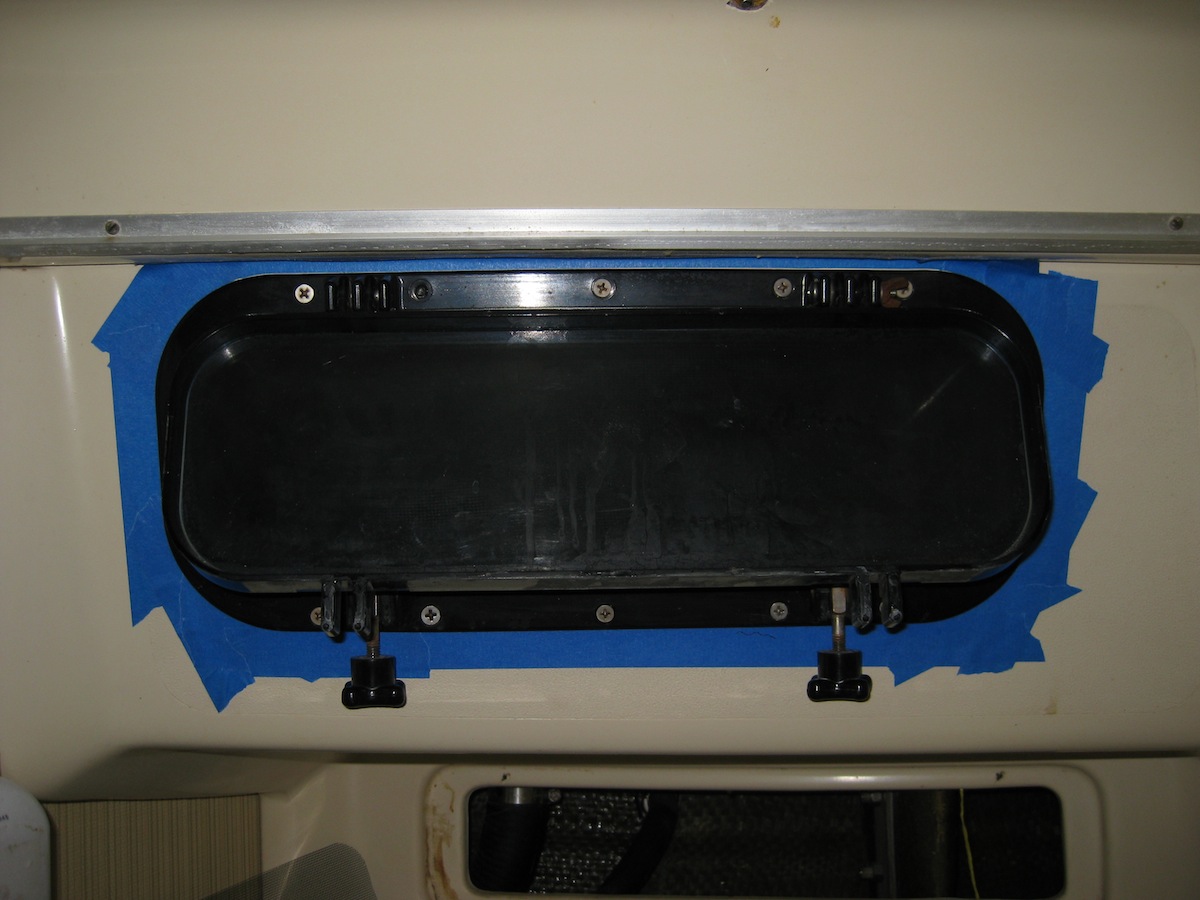
The port in the head is the only one of our ports that open, and it leaked badly, both through the worn out gasket and around the bedding. When we got the boat, this had gone on long enough to destroy the teak plywood access panel under it, and was beginning to water-stain the cabinetry. So this was one of the priority leaks to attend to.
Researching on the web, I had determined that these ports were the "Newport" series, made by Beckson, part number 414. Parts were still available, so I ordered a new gasket as well as a new screen, as the old one was just a screenless frame.
Then I turned my attention to the bedding. The factory bedding of these ports has two strikes against it from day one, virtually insurng that they will leak. Fortunately, both problems are easily correctable. Strike one is the bedding material. Pearson appears to have used ordinary household silicone, like the stuff you can buy at the hardware store. Although it is quite resilient as a gasket material, it has very poor adhesion properties, and will let go on any joint that "works". This brings us to the second strike. The openings for the ports are cut through both the outer cabinhouse wall and the inner liner. These are two separate pieces of fiberglass, and there is nothing stabilizing the distance between the outer and inner pieces. The port is mounted to the inner liner, and the trim ring that goes around the "snout" of the port is mounted to the cabinhouse. The only thing maintaining the distance between the inner and outer walls is the adhesion of the bedding where the snout passes through the outer wall. As stresses and temperture changes cause the liner to flex, it pulls the port in and out of the opening in the cabinhouse wall, breaking the seal there and causing leaks. These leaks are insideous, as they run down the inside of the liner and often show up at a surprising distance from the actual leak.
The fix is twofold. One part is to stabilize the distance between the inner and outer walls. This is accomplished by filling the gap with thickened epoxy, which has the additional benifit of sealing this gap all the way around. Then, even if a leak does happen, it will only go through to the inside of the inside wall, where it is easily detectable. The second part of the fix is to use a better bedding material. There is an industrial silicone compound called Dow-Corning 795. It has a substantial amount of adhesion while remaining flexible. It is so strong that commercial builders use it as the sole glazing material to hold in the large plate-glass windows on skyscrapers! I found a place locally (Kenseal in Beltsville MD) that sells the stuff in single cartridges.
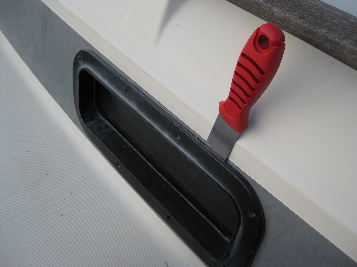
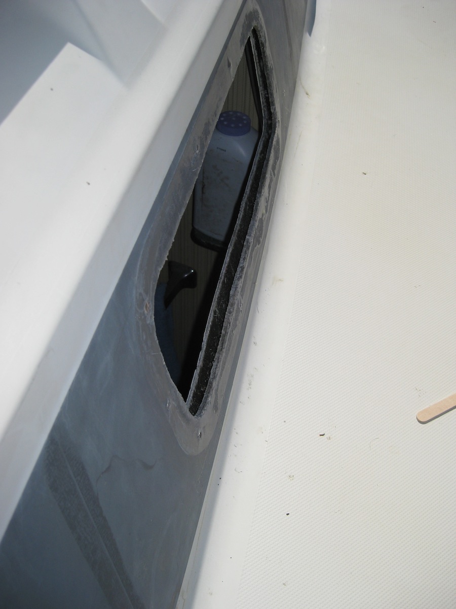
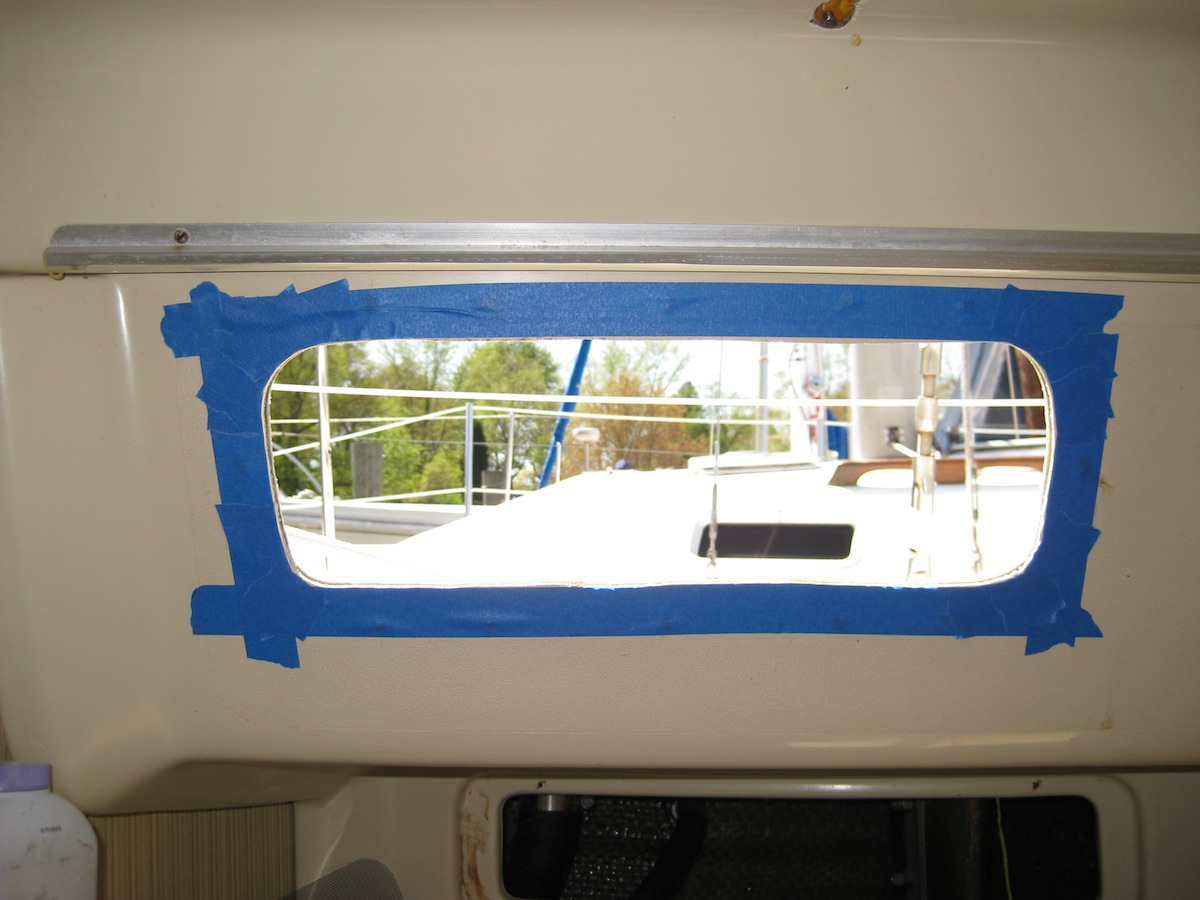
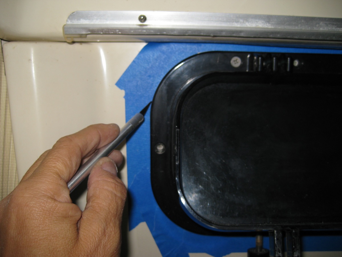
So, with new parts, epoxy, 795, and lots of blue tape in hand, I began the project in ernest. After removing the screws on the port and the trim ring, a thin-bladed scraper was used to break the old bedding free and remove the port without damage. It came out quite easily, as the old silicone had already let go at multiple places.
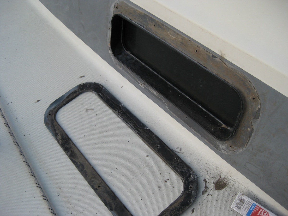
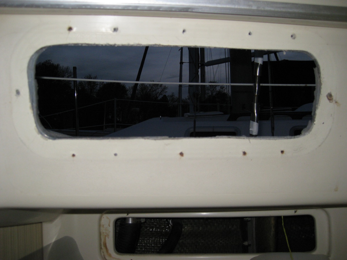
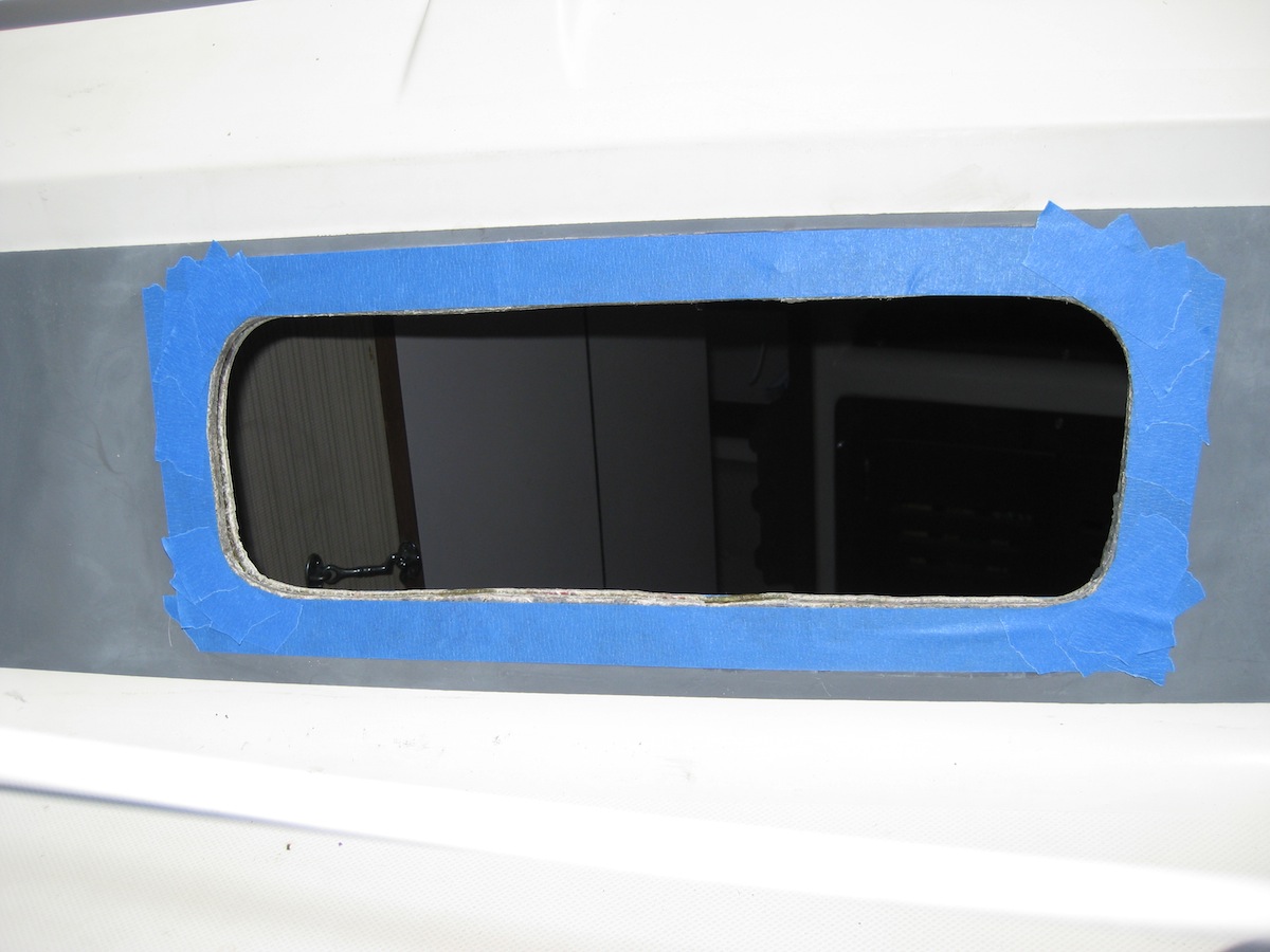
With the port out, the "floppyness" of the inner liner became immediately apparent as it bowed inward, causing a substantial variation in the width of the gap. I was going to have to find some way to hold this gap constant while I filled it. After a little thought, and casting around to see what I had to work with, I came up with an idea.
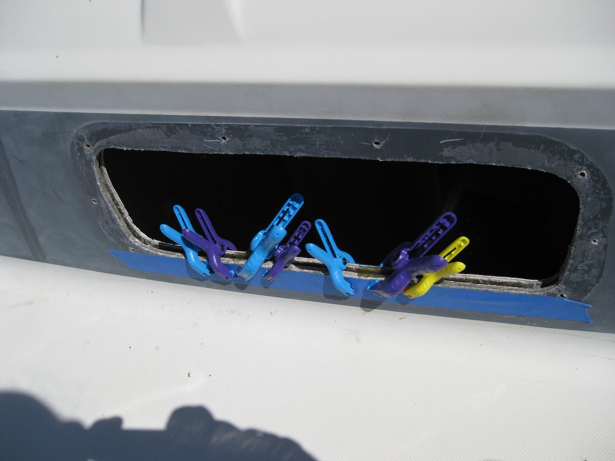
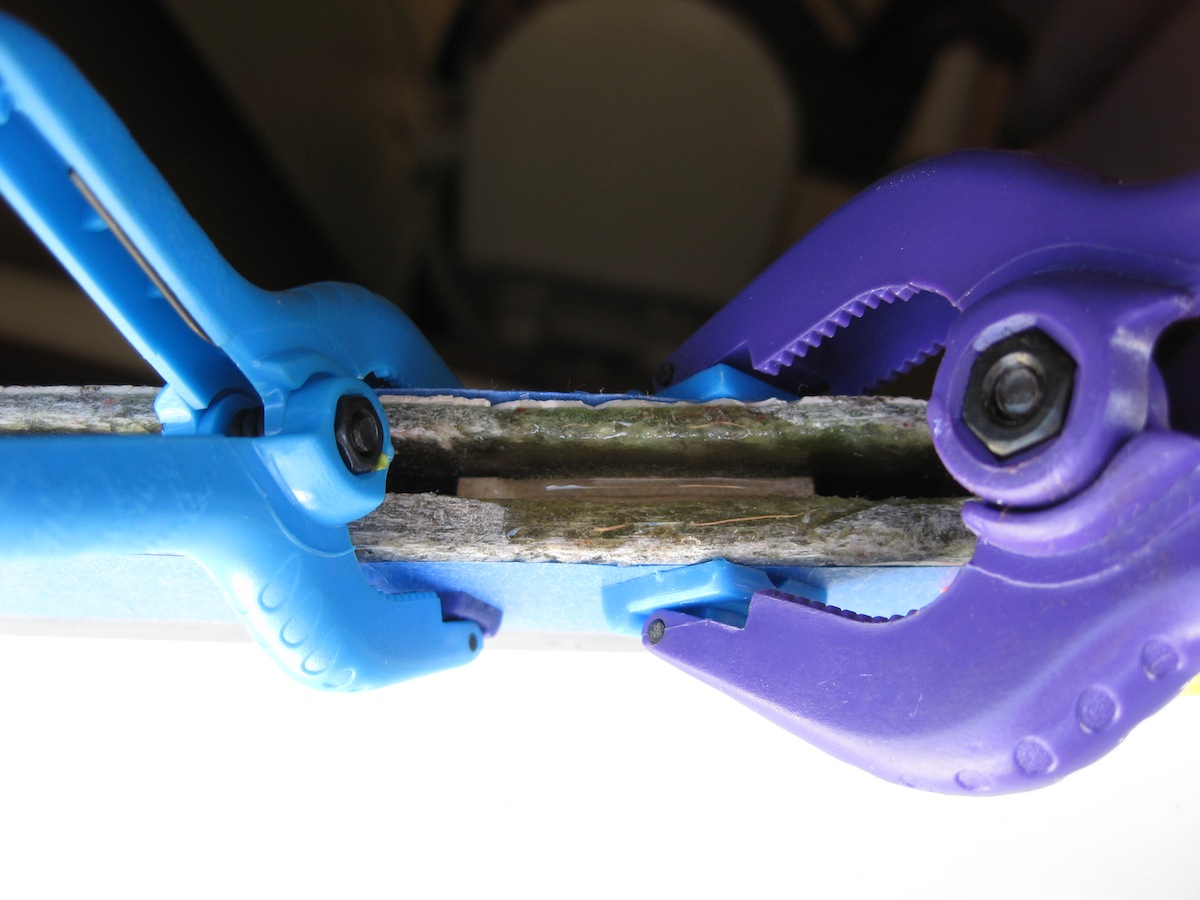
I always keep a bunch of popsicle/craft sticks on hand for working a bead on sealant. What I discovered was that a few pieces of popsicle stick laminated together with some superglue made the perfect size shim! I made up a pair of these and epoxied them in place, using some utility clamps to hold things until the epoxy set. Repeating this around the opening as needed gave me a nice, even gap, ready for filling.
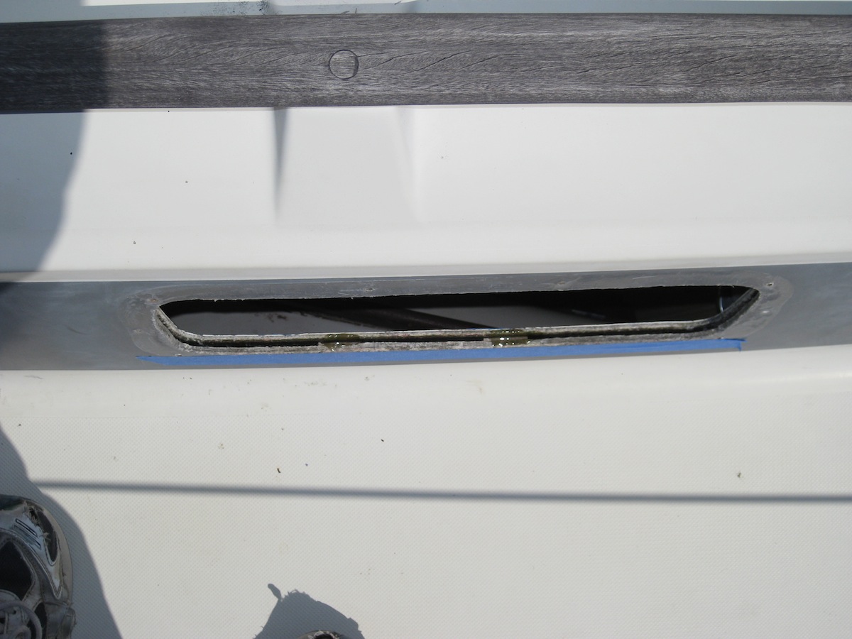
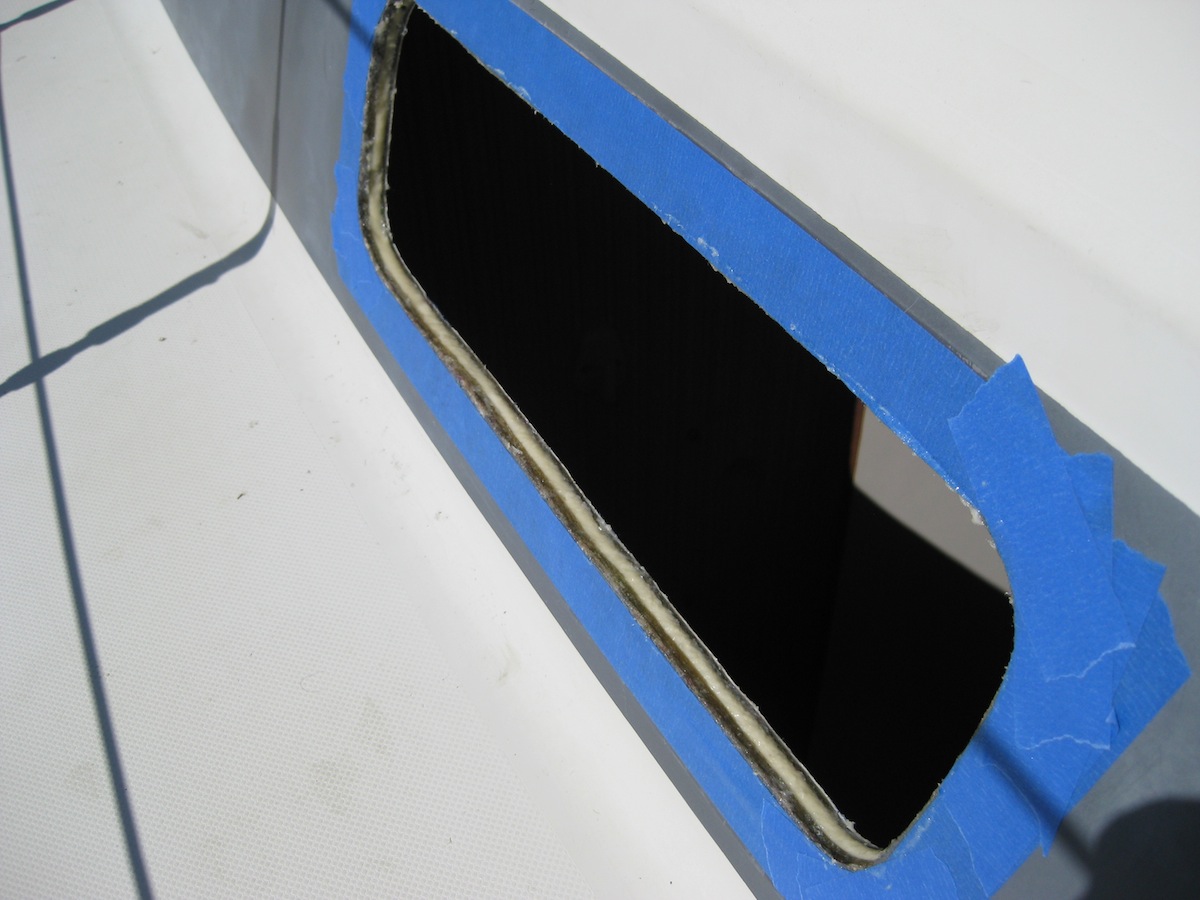
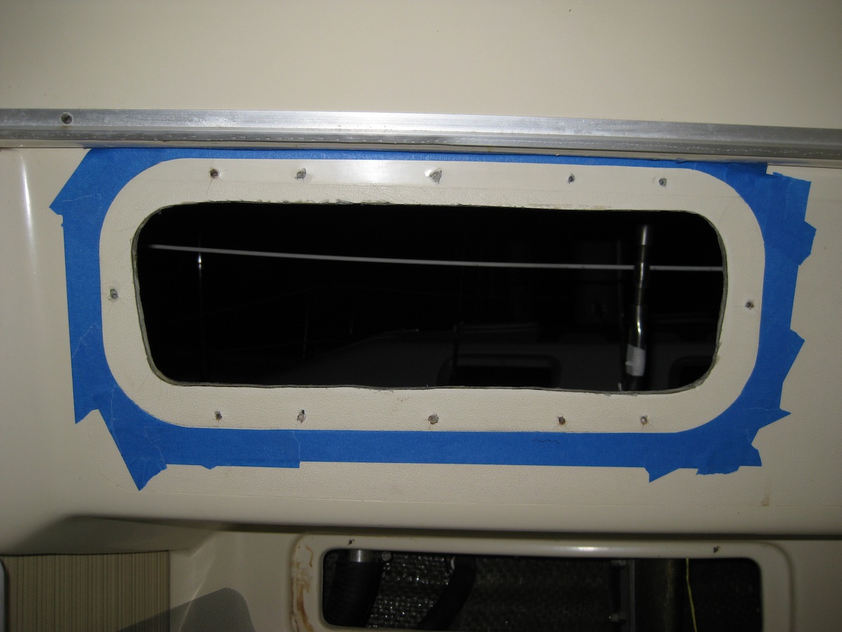
Next step was to mask off the opening on both sides to prevent getting any epoxy on the flat gelcoat surfaces that the port would seat on. Then, I mixed up a batch of West System G-Flex epoxy, with enough thickener to get it to the consistency of peanut butter, and filled the gap generously. Later, I found that even with the thickener, I had to shore-up the overhead parts with more blue tape (not shown) to keep it from sagging out of the gap.
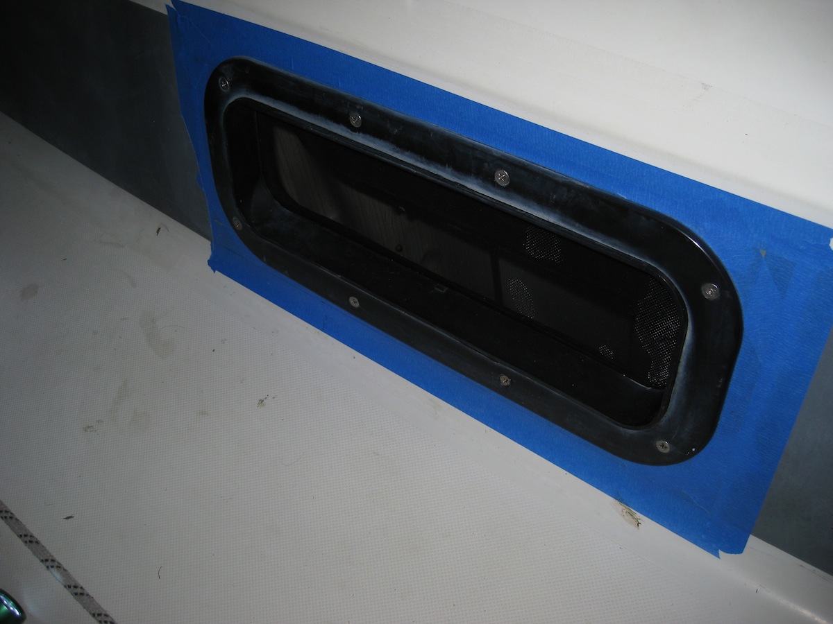
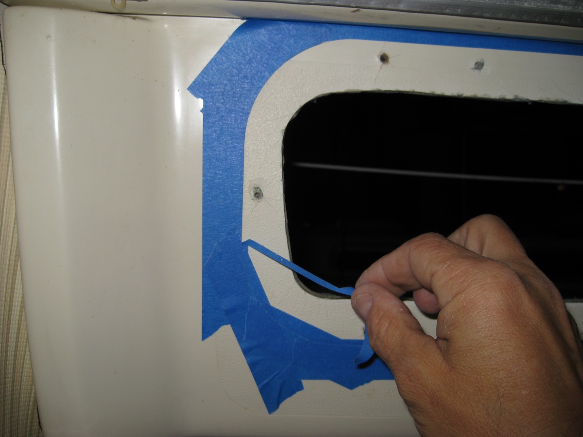
Once the epoxy was completely set, I removed the tape, thoroughly scraped and cleaned all of the bedding surfaces, and began masking for the 795 bedding adhesive. The technique I used was to lay down a line of tape that straddled the edge of the port's flange. Then, with the port dry-fitted and held in place with two screws, I used a sharp xacto knife to carefully trace the outline of the port and score the tape. The same thing was done on the outside for the trim ring. Then with the port again removed, the inner portion of the scored tape could be peeled, resulting in a perfect mask. I wanted this mask to be close and clean, as I was using black 795 to match the black port in case any squeezed out on the line between the snout and the inside edge of the trim ring, and did not want any of the black to show on the white gelcoat.
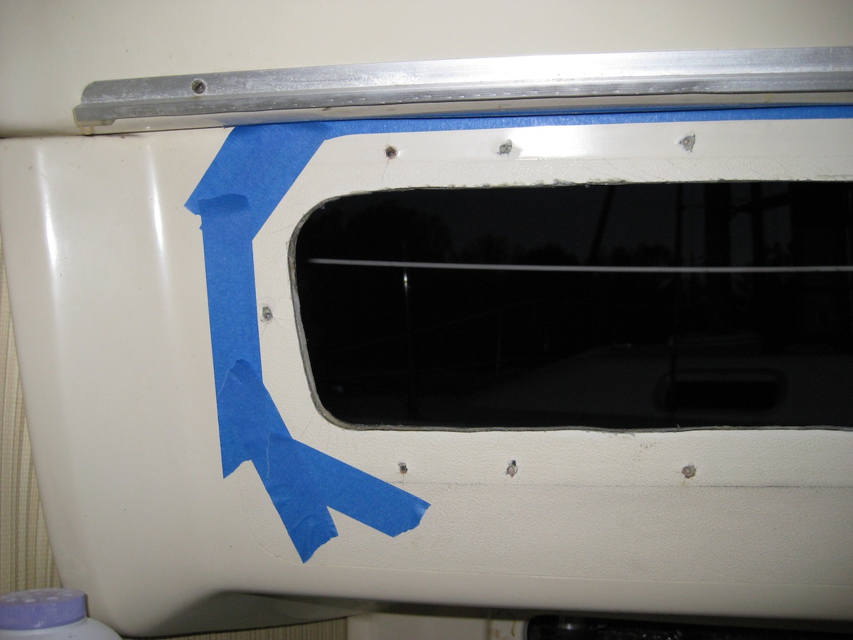
After all the prep, the actual fitting of the port was trivial. Any excess 795 that squeezed out onto the tape was easily cleaned up with a straight blade screwdriver. After 2-3 hours, the 795 has set up enough to remove the tape easily but not get black accidentally smeared all over the place. The result was a nice clean edge, and a port that never leaks!